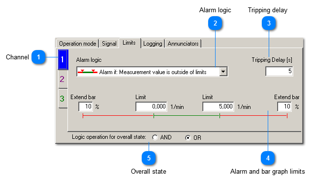
Recording is triggered when a limit was exceeded. The limits can be entered for each channel separately.
 Channel
|
|
All settings can be entered independently for each channel. Different parameters, like vibration and frequency can be mixed in one diagram. The number of tabs depends on the number of active channels.
| |
|
 Alarm logic
You may decide whether recording is triggered if
-
the signal is inside the limits -
the signal is outside the limits
|
|
 Tripping delay
|
|
If short signal peeks shall not start a recording you may enter here a minimum duration. The alarm condition must persist during this time before recording is triggered.
| |
|
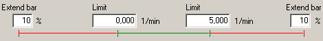
 Alarm and bar graph limits
You can enter here a lower and an upper alarm limit. The limits are indicated by red markers above the bar graph. At the same time the alarm limits set the length of the bar graph. The length can be entered in percent above / below the alarm limit.
|
|
 Overall state
The individual alarm settings of each channel determine whether an alarm event is detected. After the tripping delay is over the alarm will be set. In overall state you may select whether a single channel alarm or all alarms need to be set in order to trigger recording:
-
AND: all channels need to be in alarm condition to trigger recording -
OR: recording is triggered by an alarm condition at any channel
|
|