8. Accelerometer Cabling
Cables and connectors are typically the weakest link of a measuring chain.
In our sensor data sheets you find recommendations for suitable cables.
Choosing the right sensor cable is of particular importance for accelerometers with charge output. When a coaxial cable is subjected to bending or tension this may generate local changes in capacitance. They will result in charge transport, the so-called triboelectric effect. The produced charge signal cannot be distinguished from the sensor output. This can be troublesome when measuring low vibration with charge transducers. Therefore Metra supplies all charge transducers with a special low noise cable. This cable type has a particular dielectric with noise reduction treatment. However, it is recommended to clamp the cable to the test object.
Important: The connectors of low noise cables for charge transducers should be kept absolutely clean Dirt or humidity inside the plug may reduce insulation resistance and will thereby increase the lower frequency limit of the sensor.
As a rule, the cable length of sensors with charge output should not exceed 10 m.
IEPE transducers do not require special low noise cables. They can be connected with any standard coaxial cable.
Strong electromagnetic fields can induce error signals. This is particularly the case with charge transducers. Therefore it is recommended to route the sensor cable as far away as possible from electromagnetic sources, like generators, AC converters or motors. Do not route the cable along power lines and cross them right-angled.
Relative cable motion (cable whip) at the sensor body can cause erroneous sensor outputs. Miniature accelerometers and compression designs (i.e. Metra´s “KD” models) are particularly susceptible. This problem can be avoided by proper cable tie-down. Metra offers the cable clamps 004 and 020 for this purpose. Adhesive cable clamps or “O”-Rings are also suited as shown in the illustration below.
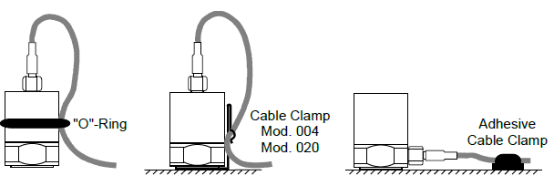
When securing the cable, leave enough slack to protect the sensor from mechanical stress by the cable.
Before starting the measurement, make sure that all connectors are carefully tightened. Loose connector nuts are a typical source of measuring errors. Do not use a pliers. Hand tightening is sufficient. A small amount of thread-locking compound can be applied on the male thread. Avoid contamination of the insulator.
Metra standard accelerometer cables may have the following connectors:
- Microdot: coaxial connector with UNF 10-32 thread
- Subminiature: coaxial connector with M3 thread
- TNC: coaxial connector with UNF7/16-28 thread and IP44
- BNC: coaxial connector with bayonet closure
- Binder 707: circular 4 pin connector with M5 thread (modified for Metra)
- Binder 711: circular 4 pin connector with M9 thread
- Binder 713: circular 4 pin connector with M12 thread and IP67
- Binder 718: circular 4 pin connector with M8 thread and IP67
- 1/4-28 UNF: 4 pin connector with 1/4-28 UNF thread
Metra offers a selection of plug adapters and couplers.
Customized cables can be supplied on demand.
Avoiding Ground Loops
The most common source of errors in connection with sensors and AC measuring instruments are ground loops. They are a result of unwanted potential differences in the electric circuit between the sensor and the instrument. Such problems usually occur along ground or earthing cables. Possible reasons are:
- Long distance between sensor and instrument
- Voltage drop over insufficient cables in the grounding network
- Measurement close to powerful electric engines which may cause considerable current transients in the grounding system
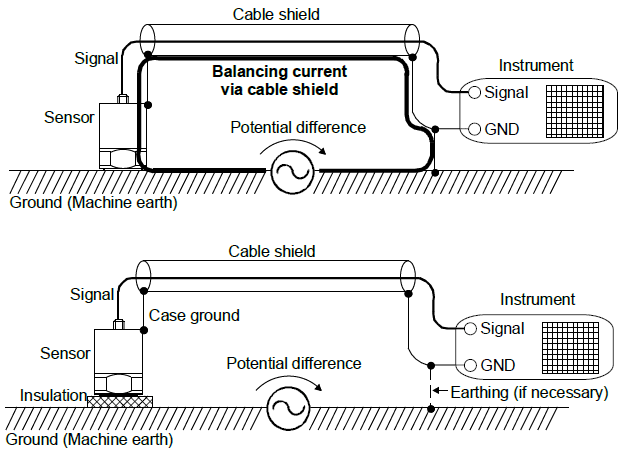
These potential differences may cause balancing currents through the shield of the sensor cable. The result are voltage drops which will be added as an error component to the sensor signal at the input of the instrument. Typically, these error signals have strong frequency components at 50 or 100 Hz or, in the presence of pulsed drives, also at higher frequencies.
For this reason the current path between the sensor mounting location and the instrument should be interrupted by electrical isolation.
The following practical method usually helps to avoid ground loops:
The entire measuring chain is grounded at only one point, if grounding cannot be avoided completely. The transducer, a preamplifier (if required) and the cable shield are insulated from ground / earth potential. If necessary, a connection with protective earth or ground is made on the instrument side.
Particularly important is a single, central grounding point in the measuring system.
We recommend to choose accelerometers with isolated base. Isolating flanges are also suitable.