
2. Piezoelectric Principle
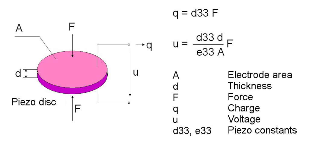
A piezoelectric material is fixed in the transducer housing. The figure below illustrates the piezoelectric effect with the help of a compression disk. This resembles a ceramic capacitor with two electrodes facing each other. A force acting perpendicular to the electrode surface causes a charge shift in the ceramic and can be picked up as a voltage across the electrodes.
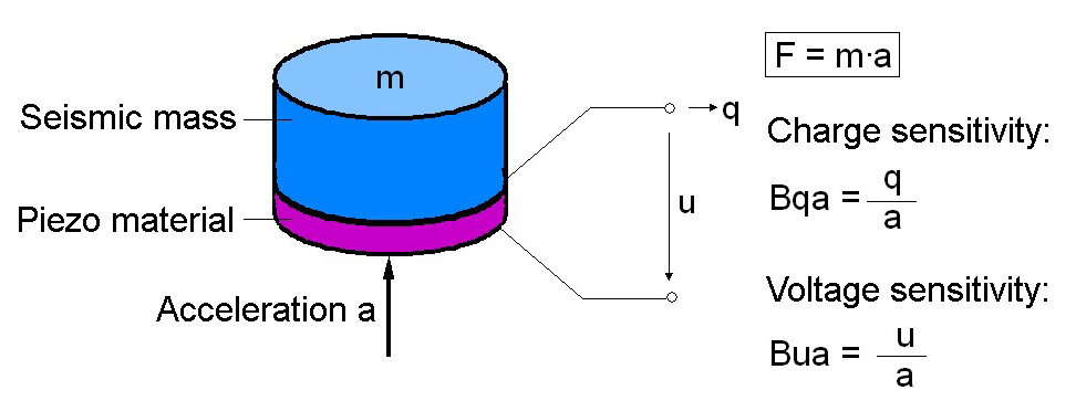
A piezoelectric accelerometer consists of two major parts:
- Piezoelectric material
- Seismic mass
One side of the piezoelectric material is connected to a rigid post at the sensor base. The so -called seismic mass is attached to the other side. When the accelerometer is subjected to motion, a gravitational force is generated which acts on the piezoelectric element. According to Newton’s Law this force is equal to the product of the acceleration and the seismic mass. By the piezoelectric effect a charge output proportional to the applied force is generated. Since the seismic mass is constant the charge output signal is proportional to the acceleration of the mass.
Over a wide frequency range both sensor base and seismic mass have the same acceleration magnitude. Hence, the sensor measures the acceleration of the test object. A piezoelectric accelerometer can be regarded as a mechanical low-pass with resonance peak. The seismic mass and the piezoceramics (plus other “flexible” components) form a spring mass system. It shows the typical resonance behavior and defines the upper frequency limit of an accelerometer. This resonance behaviour determines the upper frequency limit. In order to achieve a wider operating frequency range the resonance frequency needs to be increased. This is usually done by reducing the seismic mass. However, the lower the seismic mass, the lower the sensitivity. Therefore, an accelerometer with high resonance frequency, for example a shock accelerometer, will be less sensitive. On the other hand, a seismic accelerometer with high sensitivity has a low resonance frequency.
The illustration shows a typical frequency response curve of an accelerometer when it is excited by a constant acceleration.
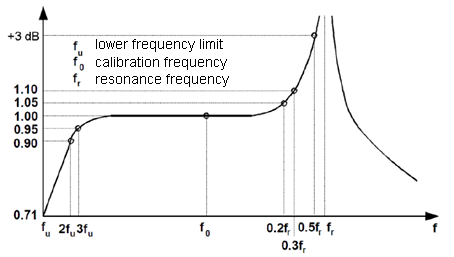
Some useful frequency ranges can be derived from this curve:
- At approximately 1/5 the resonance frequency the response of the sensor is 1.05. This means that the measured error compared to lower frequencies is 5 %.
- At approximately 1/3 the resonance frequency the error is 10 %. This is often considered as linear “frequency range”.
- The 3 dB limit with approximately 30 % error is obtained at approximately one half times the resonance frequency.
These are typical values which may vary depending on the accelerometer design.
The lower frequency limit mainly depends on the chosen preamplifier. Often it can be adjusted. With voltage amplifiers, the low frequency limit is a function of the RC time constant formed by accelerometer, cable, and amplifier input capacitance together with the amplifier input resistance.
The history of piezoelectricity: PDF