
6. Instrumentation
Transducers with Charge Output
Transducers with charge output have some special properties which require particular attention in order to obtain precise measuring results:
- Always use special low noise cables.
- The cable length must not exceed 10 meters.
- The cable should not be moved during measurement.
- All connector nuts must be tightened.
Preferably charge amplifiers should be used. It is also possible to use AC voltage amplifiers with high impedance input. Both principles are described below.
Charge amplifier
Accelerometers with charge output generate an output signal in the range of some picocoulombs (1 pC = 1000 fC) with a very high impedance. To process this signal by standard AC measuring equipment it needs to be transformed into a low impedance voltage signal.
Preferably, charge amplifiers are used for this purpose. The input stage of a charge amplifier features a capacitive feedback circuit. The feedback loop compensates the applied charge input signal. The feedback signal is then a measure of input charge. The figure shows a typical charge input stage.
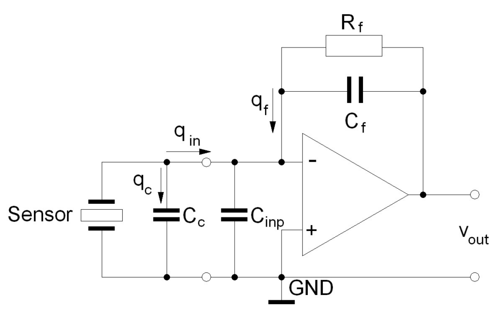
The input charge qin is applied to the summing point (inverting input) of the amplifier. It is distributed to the cable capacitance Cc,the amplifier input capacitance Cinp and the feedback capacitor Cf. The node equation of the input is therefore:

Using the electrostatic equation:

and substituting qc, qinp and qf :
Since the voltage difference between the inverting and the non-inverting input of a differential amplifier becomes zero under normal operating conditions, we can assume that the input voltage of the charge amplifier uinp will be equal to GND potential. Withuinp=0 we may simplify the equation:

and solving for the output voltage uout:

The result clearly shows that the output voltage of a charge amplifier depends only on the charge input and the feedback capacitance. Input and cable capacitances have no influence on the output signal. This is a significant fact when measuring with different cable lengths and types.
The feedback resistor Rf has the function to provide DC stability to the circuit and to define the lower frequency limit of the amplifier. At the same time Rf determines the lower frequency limit of the amplifier.
The shown circuit represents only the input stage of a charge amplifier. Other stages like voltage amplifiers, buffers filters and integrators are not shown.
Typical charge amplifiers are, for example, the M72 series signal conditioners and the IEPE100 remote charge converters made by Metra.
High-Impedance AC Voltage Amplifiers
Instead of charge amplifiers, high impedance voltage amplifiers can be used with charge mode transducers. In this case, however, the capacitances of sensor, cable, and amplifier input must be considered.
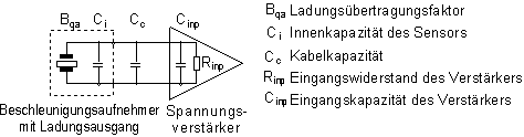
The voltage sensitivity Bua of an accelerometer with known charge sensitivity Bqa and inner capacitanc Ci s calculated:

Bqa and Ci can be found in the sensor data sheet.
Taking into account the capacitance of the sensor cable Cc and the input capacitance of the voltage amplifier Cinp, the resulting voltage sensitivity B´ua is:
B´uawill be lower than Bua. A typical 1.5 m low noise cable Model 009 has a capacitance of approximately 135 pF.
The lower frequency limit fl will also be influenced by Cc, Cinp and Rinp:
The lower frequency limit increases with decreasing input resistance.
Example: A charge mode accelerometer Model KS56 with inner capacitance of 370 pF is connected to a typical scope input with 10 MOhms input resistance and 20 pF capacitance. The sensor cable has a capacitance of 135 pF.
Result: The lower frequency limit will be at about 30 Hz.
IEPE Transducers
A special feature of IEPE compatible transducers is that power supply and measuring signal are transmitted via the same cable. So, an IEPE compatible transducer requires, like a transducer with charge output, only one single-ended shielded cable. The figure below shows the principle circuit diagram.
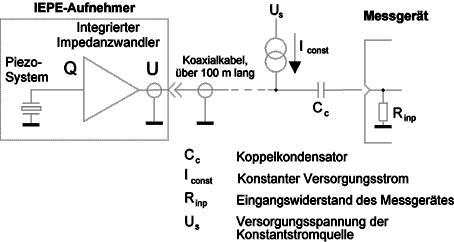
The integrated sensor electronics is powered with constant current in the range between 2 and 20 mA. A typical value is 4 mA. Some battery powered instruments even work at 1 mA.
The constant current Iconst is fed into the signal cable of the sensor.
The supply current and the length of the cable may influence the upper frequency limit.
The de-coupling capacitor Cc keeps DC components away from the signal conditioning instrument. The combination of Cc and Rinp acts as a high pass filter. Its time constant should be sufficiently high to let all relevant low frequency components of the sensor signal pass.
Important:
- Do not apply a voltage source without constant current regulation to an IEPE transducer. This may damage the transducer immediately.
- False polarization of the sensor cable may immediately destroy the built-in electronics.
From the diagram below can be seen that IEPE compatible transducers provide an intrinsic self-test feature.

By means of the bias voltage UBIAS at the input of the instrument the following operating conditions can be detected:
- UBIAS < 2 V: short-circuit or negative overload
- 2 V < UBIAS < 18 V: O.K., output within the proper range
- UBIAS > 18 V: positive overload or input open (cable broken or loose connector)