
7. Accelerometer Mounting
Choosing the optimum mounting arrangement will significantly improve the accuracy.
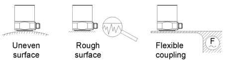
For best performance, particularly at high frequencies, the accelerometer base and the test object should have clean, flat, smooth, unscratched and burr-free surfaces.
A scratched accelerometer base can be applied to a lapping plate for restoration of flatness. If lapping is not possible, other machining processes such as grinding, spot facing, milling, turning, etc., can produce acceptably flat mounting surfaces.
It is also important to provide a stiff mechanical connection between the sensor and the source of vibration. Sheet metal or plastic parts and other thin and flexible components are unsuited for accelerometer mounting.
Errors due to unwanted sensor vibrations can be reduced by symmetric mounting. The weight of the sensor including all mounting components should be low compared to the weight of the test object. As a rule the sensor should not weigh more than 10 % of the test object.
Misalignment of the sensor axis and the measuring directions should be kept as low as possible, particularly if transverse vibration with high magnitude is present. When using screw mounting, make sure that the screw is not longer than the threaded hole. There must be no gap under the sensor.
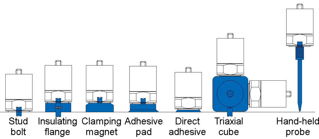
The following mounting methods are are commonly used for accelerometers:
- Stud mounting with stud bolt, insulating flange or adhesive pad
- Magnetic base
- Adhesive by bee wax, cyanoacrylate (e.g. the gel-like Loctite 454) or epoxy glue
- Mounting cube for triaxial measurement with three uniaxial accelerometers
- Accelerometer probe by hand pressure
- Accelerometer with movable probe tip (KST94)
The diagram compares the typical high frequency performance of some mounting methods as a result of added mass and reduced mounting stiffness. Coupling resonances are caused by additional masses and reduced rigidity.
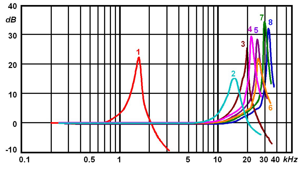
1: hand-held probe
2: thin double-sided adhesive tape with screwed adhesive pad
3: bees wax with screwed adhesive pad
4: instant glue with screwed adhesive pad
5: bees wax, directly
6:thin double-sided adhesive tape, directly
7: instant glue, directly
8: stud bolt
The accelerometers made by Metra may have the thread sizes M3, M5, M8 and M10.
Many sensor types are available with option “/01” including an accessory kit. The kit includes most suitable mounting accessories.